
 |
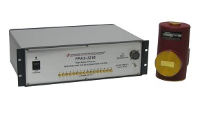
FPAS-3216 | |
|
The New Femto-Second Laser Pulse Acquisition System was developed for high speed laser “Pump-Probe” spectroscopy providing 16 to 1024 channel simultaneous sampling from Multi-Element HgCdTe (MCT) Detector Arrays. The FPAS integrates and captures detector signals from short pulse, high-energy laser systems with excellent linearity and a true 16-Bit resolution.
The FPAS provides all of the system components required to acquire Femto-Second spectroscopy data, including user inputs to monitor stepper motor positions, and outputs to control mirror path length position. The system includes preamplifiers, integrators, Sample & Holds , Multiplexers, 16-Bit A/D Converter, FIFO Memory, Digital IO Computer Card and Host Computer System with custom LABVIEW tm Software for complete control and data presentation.
The High-speed data acquisition system has been developed by ISDC to provide a complete system for interfacing to an MCT (HgCdTe), or InSb detector array to allow high-speed acquisition from short duration laser pulses. The system includes preamplifier, bias network, and Sample and Hold circuitry for each element in the array, and couples these channels through a high speed multiplexer to an A/D converter. The ADC is then clocked into a FIFO memory to allow synchronous writing and a synchronous reading of the dual port FIFO. This allows the data to be stored in the FIFO by the synchronous acquisition circuitry based on the pulse repetition rate, and the read out is accomplished through a high-speed digital I/O card installed in the host computer.
The acquisition starts with the rising edge of the Laser sync pulse, which initiates the delay time. The laser fires very shortly after this rising edge. The MCT signal appears approximately 50-100 ns after the laser fires. The Sample pulse then acquires the preamplifier output signal and Holds until cleared. As soon as the sample interval is completed the first channel is multiplexed to the A/D input, then the A/D conversion is done in 1 usec and clocked into the FIFO memory. When Channel 1 is clocked into memory, Channel 2 is multiplexed to the A/D input and read, then it is clocked into the FIFO. The FIFO empty signal indicates that there is data in the FIFO and the host PC with the digital I/O card monitors this line and begins reading the data from the FIFO as soon as it is available. The entire array is readout and cleared before the next 1Khz rising edge appears to fire the laser again. This process repeats until stopped by the user.
The External Inputs can be configured for detectors or a user provided -5 to +5 Volt signal. The signal is sampled and acquired at the same time, using the same integration parameters as the internal detector channels. This allows the user to input analog data from other devices, such as mirror position and also allows for a single element detector to monitor the laser pulse amplitude to correct for variations in the laser energy, which can greatly reduce noise.